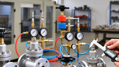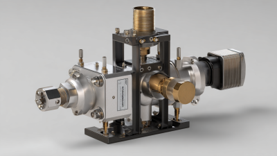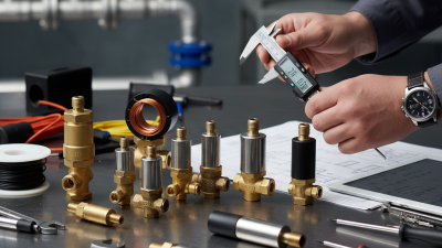

Industrial processes depend on stable, measurable flow. A few degrees of valve travel can affect pressure, product quality, energy use, and equipment wear. The right Flow Control Valve helps operators manage these variables across water treatment, chemical processing, power generation, and manufacturing. But no single design fits every line.
Grand View Research’s Industrial Valves Market Size, Share & Trends Analysis Report estimated the global industrial valves market at USD 79.5 billion in 2023. It projected a 4.4% compound annual growth rate from 2024 to 2030. These figures cover industrial valves broadly, not flow-control products alone, so they show market scale rather than a direct forecast for this category. Selection still comes down to operating conditions.
This guide compares ten valve types and product options through practical factors: control accuracy, pressure and temperature range, fluid compatibility, maintenance needs, and installation cost. A globe valve may suit precise throttling; a butterfly valve can offer compact control in larger pipes. Small details matter. Check the actual flow curve, actuator response, materials, and failure position against the process specification. Manufacturer data sheets and qualified engineering review should support the final choice. Even a well-known valve can underperform when sizing assumptions are wrong. That part deserves a second look.
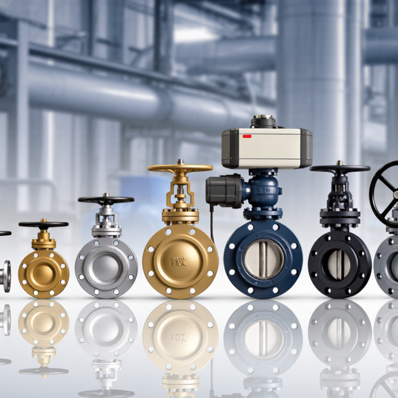
Flow control valves regulate industrial systems by changing the opening available to a moving fluid. A smaller opening increases resistance and can lower downstream flow or pressure; a larger one allows more through. In practice, a sensor and controller may adjust the valve as demand changes. Picture a cooling-water line: when a machine heats up, the valve opens to send more water through its exchanger. Small movements matter.
Valve selection depends on the fluid, operating pressure, temperature, and required flow range. A valve that is oversized may operate almost closed, making control unstable. One that is undersized may restrict flow even when fully open. The U.S. Department of Energy’s Improving Pumping System Performance sourcebook estimates that pumping systems use nearly 20% of global electricity, and 25–50% of energy in some industrial plant operations. Those figures describe pumping systems, not savings guaranteed by a valve; they do show why reducing avoidable resistance deserves attention.
Operators should compare flow and pressure readings before and after adjustment, while checking for vibration, noise, and temperature changes. Not magic. A control valve cannot correct a clogged strainer, poor pipe layout, or an inaccurate sensor. I’d also be cautious about assuming the lowest flow is best: inadequate cooling or lubrication can create a different problem. Calibration and regular inspection keep control decisions tied to actual operating conditions.
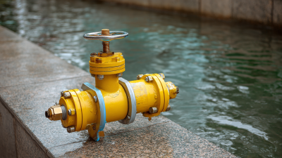
Key Types of Industrial Flow Control Valves
Industrial flow-control valves regulate liquid or gas flow by changing the passage opening. Globe valves offer precise throttling, but their pressure drop can be substantial. Butterfly valves are compact and suit large pipes. Ball valves usually provide fast isolation; characterized designs can also modulate flow. Needle valves handle small, carefully adjusted streams. Diaphragm valves can suit corrosive fluids, depending on the wetted materials. No type fits every service.
Selection starts with the fluid, operating pressure, temperature, required range, and actuator response. An oversized valve may hunt near its seat; an undersized one can restrict capacity. The U.S. Department of Energy’s Improving Pumping System Performance: A Sourcebook for Industry (2006) reports that pumping systems use nearly 20% of global electrical demand and 25–50% of energy in some industrial operations. That context makes valve pressure loss worth checking, though the figures describe pumping systems, not valves alone.
Tips: Compare the valve’s rated flow coefficient with expected operating conditions, not just pipe size. Check cavitation risk and material compatibility. Test the selected valve under realistic process conditions when possible. A tidy calculation may still miss changing fluid properties. That deserves a second look.
The 10 best flow control valves for industrial applications depend on the fluid, pressure, temperature, and required accuracy. Globe valves offer steady throttling in steam and water lines, while butterfly valves suit larger pipes where space is limited. Ball valves can provide quick shutoff, but standard designs may offer less precise control at low flow. Needle valves handle fine adjustments in small lines. Diaphragm and pinch valves are useful for corrosive or particle-laden fluids because the process fluid contacts fewer moving parts. Small details matter.
Plug, eccentric plug, and segmented ball valves can manage demanding flow conditions, while pressure-independent control valves help maintain steadier flow as system pressure changes. No type fits every duty.
The U.S. Department of Energy’s Improving Pumping System Performance sourcebook reports that pumping systems account for nearly 20% of global electricity demand and 25–50% of energy use in some industrial plant operations. That is system-wide energy, not a valve-only saving.
Still, a poorly sized valve can create excess pressure loss and increase pumping demand. Check the valve’s flow coefficient, materials, actuator response, and maintenance access against actual operating data. Not always an easy choice. Real plants often change, and sizing assumptions deserve a second look.
Comparing flow control valves starts with the duty point, not the catalog’s largest flow number. Record minimum, normal, and peak flow, plus inlet and outlet pressure at each condition. Compare the required flow coefficient, such as Cv or Kv, with the valve’s usable range. A valve sized near its limit may lose control authority; an oversized one can hunt at low flow.
Check more than capacity. Review allowable pressure drop, shutoff leakage, response time, and controllability across the expected turndown. Confirm body and trim materials suit the fluid chemistry, temperature, solids, and erosion risk.
Ask whether published limits apply continuously or only briefly. Test it cold. Startup viscosity and low ambient temperatures can change response, while a warm steady-state test may hide that weakness.
Compare fail position, actuator force, signal compatibility, and maintenance access alongside operating limits. For example, a valve meeting peak flow at 6 bar differential may be unsuitable if the system normally runs at 1 bar.
Request sizing calculations and test conditions, then verify critical points with a qualified engineer. One datasheet figure is not proof; actual piping and instrumentation introduce uncertainty.
Selecting a flow control valve starts with the process, not the catalog. Record the fluid, normal and peak flow, operating pressure, temperature, and acceptable pressure drop. A valve sized only for maximum flow may struggle to control low-flow conditions. Check the manufacturer’s flow coefficient data against actual operating points, and confirm that the valve material suits the fluid. Small compatibility errors can lead to leakage, wear, or unexpected maintenance.
Tips: Ask operators how the line behaves during startup and shutdown. Check whether solids, bubbles, or changing viscosity affect control. Choose an actuator and signal type that match the control system, then confirm the required fail position with the process safety team. Leave room for inspection and removal; a valve that fits on paper may be awkward beside a hot pipe or crowded support.
For example, a cooling-water line may need stable control across seasonal temperature changes, while a dosing line may require precise adjustment at low flow. Review both cases with measured data when possible. No chart captures every startup. That matters. I would also question assumptions about “typical” service: actual site conditions can differ from the design sheet, and the difference deserves a second check.