How to Choose a Pneumatic Flow Control Valve
Choosing a Pneumatic Flow Control Valve is not just a matter of matching a fitting. The right valve helps regulate actuator speed, maintain predictable motion, and reduce wasted air. The wrong choice can cause a cylinder to move too quickly, hesitate, or behave differently under changing loads. Small differences matter.
This guide explains how to compare meter-in and meter-out control, assess required flow and operating pressure, and check port size, connection type, and installation space. It also covers adjustment range, response, materials, and maintenance access. Fluid-power author Andrew Parr’s work offers a useful foundation. A practical principle, paraphrased from his guidance, is: “Choose components for the circuit’s actual pressure, flow, and operating conditions—not appearance alone.” This is a paraphrase, not a verbatim quotation.
Before selecting a valve, identify the actuator, supply pressure, desired cycle time, and load variation. Then consider whether the application needs one-way flow control, bidirectional adjustment, or a compact valve mounted directly at the cylinder. Measure before choosing. A catalogue’s maximum flow figure may not reflect performance in your circuit. Tubing length, fittings, exhaust restrictions, and air preparation can all affect movement. Real systems are rarely tidy, and a small pressure drop may change the result. Use manufacturer specifications, confirm compatibility, and test adjustments under representative operating conditions. The sections that follow provide a practical framework for making that choice—and for revisiting it when the machine’s behavior does not match expectations.
Understand How Pneumatic Flow Control Valves Regulate Airflow
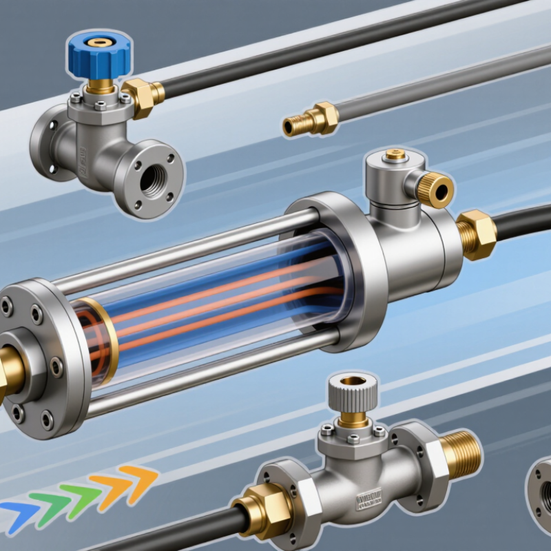
A pneumatic flow control valve regulates airflow by restricting passage area, not by generating pressure. In a cylinder circuit, turning a needle adjusts how much air passes through, changing piston speed. A one-way design may allow free flow in one direction while throttling flow in the other. That distinction matters. Meter-out control, which restricts exhaust air, can help a loaded cylinder move steadily. A small adjustment can make a visible difference: a rod that once snapped forward may extend smoothly. Set the valve gradually, then test it under the real load and operating pressure. A bench setting may behave differently on a warm, vibrating machine.
Choose a valve using the required flow rate, working pressure, tubing, and actuator behavior—not thread size alone. An undersized passage can cause sluggish movement and pressure loss; excessive restriction can make motion unstable. The U.S. Department of Energy’s 2016 Improving Compressed Air System Performance sourcebook reports that leaks can waste 20–30% of compressor output. That figure concerns system leakage, not flow-control valves, but it highlights why airflow deserves careful attention. Check fittings and tubing during commissioning, too. I would not treat a quiet valve as proof of correct flow; measure cycle time and watch the actuator through repeated strokes. Reliable tuning takes observation, and sometimes the first adjustment is wrong.
Identify the System’s Pressure, Flow, and Speed Requirements
Before choosing a pneumatic flow control valve, define the pressure, airflow, and actuator speed the system actually needs. Measure pressure while the actuator is moving, not only at rest; a gauge reading can fall under load. Record the cylinder bore, stroke, cycle time, and expected load. These details help estimate airflow and show whether the supply can keep up. Numbers can mislead. Long tubing, small fittings, and exhaust restrictions can all slow motion.
Match the valve’s flow capacity to the required speed at the system’s working pressure. An oversized valve may make adjustment touchy, while an undersized one can limit speed and cause delays. For many double-acting cylinders, metering exhaust air provides steady motion, but the load and circuit design matter. Test under load. Adjust the valve gradually, then watch the cylinder through repeated cycles for drift, sticking, or uneven movement. A calculation is a useful start, not a guarantee; real systems have friction and pressure changes that are easy to overlook.
Compare Valve Types and Flow-Control Configurations
A pneumatic flow control valve regulates actuator speed by limiting airflow, but valve type and placement matter. A bidirectional needle valve restricts flow in both directions. It suits applications where both strokes need similar speed adjustment. A one-way flow control combines an adjustable restriction with a check valve. Air passes freely one way and is throttled the other, allowing separate behavior during extension and retraction.
For many cylinder applications, meter-out control restricts exhaust air near the cylinder port. This can help produce steadier motion because trapped air cushions the piston. Meter-in control restricts incoming air and may suit loads that resist movement, though compressible air can make speed less consistent. Neither setup is universally best. Test the actuator with its actual load, tubing length, and operating pressure.
A small needle adjustment can noticeably change cycle time. Make changes gradually, then watch for jerky starts, delayed stops, or excess noise. That matters. A valve mounted close to the cylinder often gives more predictable control than one far upstream, where tubing volume affects response. Still, access and contamination risks can influence placement. A pressure-compensated flow control may help when supply pressure varies, but it cannot correct every load-related speed change. Recheck settings after maintenance or a change in tooling.
How to Choose a Pneumatic Flow Control Valve - Compare Valve Types and Flow-Control Configurations
| Valve type |
Flow behavior |
Typical configuration |
Best suited for |
Selection considerations |
| Bidirectional needle valve |
Adjusts flow in both directions through a variable restriction. |
Installed in the line where flow needs to be limited; the same setting affects supply and exhaust flow. |
Simple flow adjustment where directional independence is not required. |
Compact and straightforward, but may make actuator speed harder to tune when the two travel directions need different settings. |
| One-way throttle-check valve, meter-out |
Restricts exhaust flow from the actuator while allowing relatively free flow in the opposite direction. |
Place at the cylinder port and orient it so air leaving the cylinder passes through the adjustable restriction. |
Common choice for controlling pneumatic cylinder speed, especially when a load may assist or overrun the actuator. |
Often provides steadier motion by maintaining backpressure in the cylinder. Confirm that the resulting backpressure is acceptable for the actuator and application. |
| One-way throttle-check valve, meter-in |
Restricts air entering the actuator and allows relatively free exhaust flow. |
Place at the cylinder port and orient it so incoming air passes through the adjustable restriction. |
Applications where controlling incoming air is suitable and the load does not tend to drive the actuator ahead of the supplied air. |
With changing or overrunning loads, motion may be less stable than with meter-out control. Test the complete actuator and load under operating conditions. |
| Proportional flow-control valve |
Varies airflow in response to an electrical command rather than only a manual adjustment. |
Integrated into a controlled pneumatic circuit, typically with a suitable controller and any required position or process feedback. |
Applications needing adjustable airflow during operation, repeatable settings, or integration with automated control. |
Check the required flow range, response, control signal, air quality, and whether feedback is needed. Performance depends on the valve and system design. |
| Fixed orifice / fixed restrictor |
Provides a non-adjustable restriction to airflow. |
Installed in the supply or exhaust path where a stable, preset restriction is required. |
Cost-conscious applications with a known operating condition and no need for routine speed adjustment. |
Simple and tamper-resistant, but changes to supply pressure, load, or circuit conditions can change actuator behavior; select the orifice for the actual application. |
Practical selection note: Pneumatic flow and actuator speed depend on factors such as pressure, load, tubing, fittings, and exhaust conditions. Confirm the valve’s rated flow capacity and connection size against the system, then adjust and test the circuit at its normal operating conditions.
Check Port Size, Thread Type, and Material Compatibility
A pneumatic flow control valve must match the tubing and the system’s expected airflow. Check the port size against the tube’s outside diameter and the required flow rate; a small port can restrict a cylinder, while an oversized valve may be harder to adjust precisely. Read the fitting specifications, not just the valve body. Thread type matters: NPT threads are tapered, while BSPP threads are parallel and typically rely on a sealing washer or O-ring. They may appear similar, but they are not automatically interchangeable. A forced fit can damage threads or cause leaks.
Tips: Confirm the thread standard before ordering. Compare the valve marking with the machine drawing, then test the connection for leaks at operating pressure. A quick visual check is not enough.
Material compatibility deserves equal attention. Consider the compressed air, lubricant, moisture, temperature, and cleaning agents the valve will encounter. Aluminum or brass bodies suit many general-purpose systems; stainless steel may be preferable in corrosive or washdown settings. Check that seals, such as NBR or FKM, tolerate the actual temperature and fluid exposure. These details are easy to overlook. One weak seal can undermine an otherwise correct selection. If the application conditions are uncertain, verify them with the equipment documentation or a qualified supplier before installation.
Install, Adjust, and Test the Selected Valve
Mount the valve close to the cylinder or actuator when practical, so the air line stays short and responsive. Check the flow arrows and port labels before connecting tubing. For many cylinder applications, meter-out control gives steadier motion by restricting exhaust air; confirm the circuit design before choosing that arrangement. Depressurize the system before installation. Keep threads clean, use fittings suited to the tubing, and avoid overtightening. Small details matter.
Start with the adjustment screw nearly closed, then increase flow gradually while the machine runs at a safe, low pressure. Watch the moving part through its full stroke. It should travel smoothly, without stalling or slamming at either end. Make small changes, and wait for each one to take effect. Too much restriction can cause hesitation; too little can make motion abrupt. That balance can take a few tries.
Test repeated cycles under normal operating conditions, not just one quick stroke. Listen for hissing, check connections with an appropriate leak-detection method, and confirm the actuator reaches its intended positions consistently. Record the final setting and operating pressure for future checks. If speed changes over time, inspect for contamination, worn seals, or a loose adjustment. One imperfect test is not enough; repeat it after the system warms up.