
Rotary Actuators turn compressed air, hydraulic power, or electricity into controlled rotation. In 2026, choosing among them means matching torque, angle, speed, precision, and duty cycle to the actual job. Small motion. Big consequences. A packaging line may need a quick quarter-turn; a robot joint may demand repeatable positioning through thousands of cycles.
The market context is clear, though it is not actuator-specific. The International Federation of Robotics’ World Robotics 2024 report recorded 541,302 industrial robot installations in 2023, bringing the global operational stock to about 4.28 million units. IFR President Marina Bill said, “The global operational stock of industrial robots reached a new record of about 4.28 million units.” That growth helps explain why actuator choice matters in automated production, but it should not be mistaken for a rotary-actuator market forecast.
This guide compares the main types: pneumatic vane and rack-and-pinion designs, hydraulic actuators, electric servo rotary actuators, and precision gear-driven options. Each has trade-offs. Pneumatic units are often compact and fast; electric models can offer precise positioning and easier integration with control systems. Hydraulic designs suit demanding torque needs, but require careful attention to fluid systems and maintenance. There is no universal winner. A datasheet cannot reveal every vibration, load variation, or installation constraint on a factory floor. The best choice depends on measurable requirements—and on details engineers sometimes overlook.
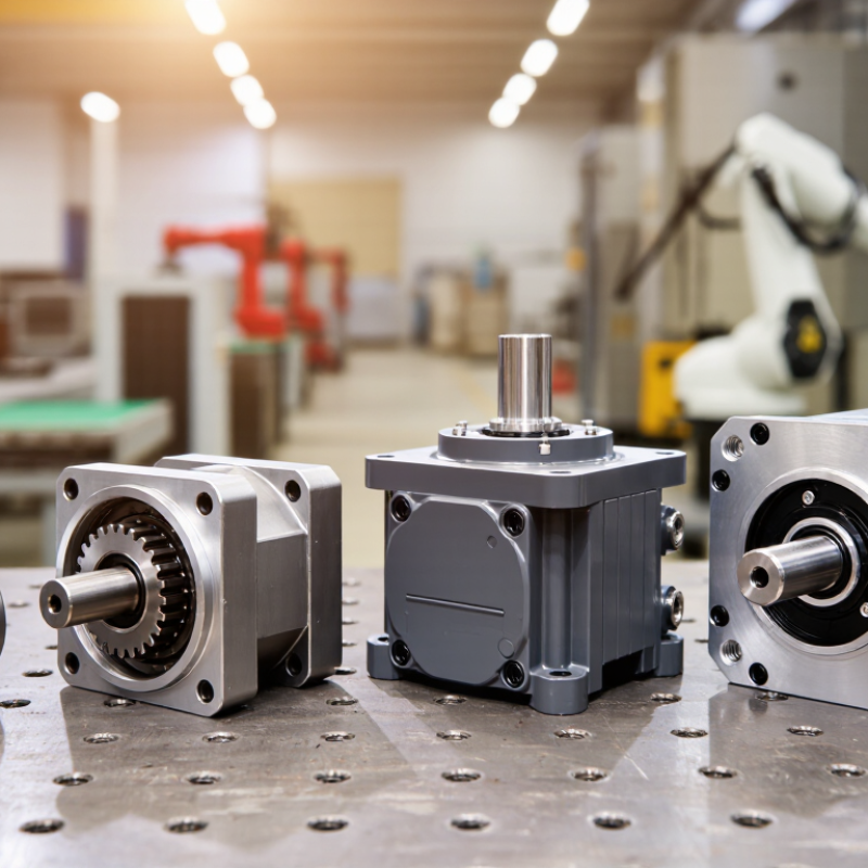
A rotary actuator turns supplied energy into rotational motion. Its shaft moves a valve, arm, or indexing table. Unlike a motor designed for continuous rotation, many actuators travel through a set angle, such as 90 degrees. The energy source creates the motion; internal parts shape its force and range.
Simple idea. Not always simple sizing.
Types are commonly classified by power source and drive mechanism.
Pneumatic models use compressed air and often suit quick, repeated movements.
Hydraulic models use pressurized fluid when high torque is needed in a compact space.
Electric actuators use a motor and gearing, offering precise positioning and convenient control.
Mechanism-based categories include vane, rack-and-pinion, and helical designs.
A vane actuator turns as air or fluid pushes a blade inside a chamber.
In a rack-and-pinion unit, a moving rack rotates a meshing gear.
The details matter.
For a real application, compare torque, rotation angle, speed, duty cycle, and available energy. A valve that moves occasionally may need different control from a table indexing dozens of times per minute. Check backlash and position feedback, too. A stated torque value alone can mislead; pressure, temperature, mounting, and load all affect performance.
The categories overlap, and choosing by label alone is tempting. It deserves a second look.
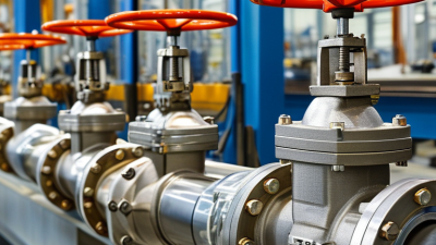
What Are the Top Types of Rotary Actuators in 2026?
Pneumatic Rotary Actuators: Vane and Rack-and-Pinion Designs
Pneumatic rotary actuators turn compressed air into controlled shaft rotation. Two common designs are vane and rack-and-pinion. A vane actuator uses air pressure on a blade inside a chamber, rotating the connected shaft through a set angle. Its compact housing suits tight spaces and straightforward quarter-turn tasks. Fewer moving parts can simplify maintenance. However, available torque and rotation angle depend on the design and operating pressure.
Rack-and-pinion actuators use air-driven pistons to move toothed racks, which turn a central gear. They can deliver higher torque across many sizes and are available in double-acting or spring-return configurations. The trade-off is more components, including seals and gear teeth that need suitable lubrication and clean, dry air. That sounds simple. It isn’t always. A poorly matched actuator may stall when a valve sticks or process pressure rises.
Tips: Size the actuator using the required torque, supply pressure, duty cycle, and safety margin—not shaft size alone. Check the torque curve across the full rotation, especially when operating a valve. Confirm end-stop settings and air connections before commissioning. These checks take time, but skipping one can lead to unreliable motion.
What Are the Top Types of Rotary Actuators in 2026?
Hydraulic Rotary Actuators: High-Torque Options for Heavy Loads
Hydraulic rotary actuators suit applications where compact equipment must turn heavy loads with controlled force. Think of a loader attachment pivoting under load, or a steel-processing fixture rotating a large workpiece. Their torque comes from pressurized fluid acting on internal vanes or pistons. That makes pressure, displacement, and mechanical efficiency key selection factors.
For a practical estimate, consider an actuator with 100 cm³/rev displacement operating at 210 bar. The standard pressure-displacement equation gives about 334 N·m of theoretical torque per revolution. At 85% mechanical efficiency, the output is roughly 284 N·m. This is an illustrative calculation, not a guaranteed rating. The National Fluid Power Association’s technical resources explain the pressure-and-flow principles behind hydraulic power; ISO 4413:2010 sets general safety requirements for hydraulic systems. Check the actuator maker’s verified torque curve for real operating conditions.
Hydraulics can deliver high torque in a relatively small package, but heat, leakage, and fluid cleanliness matter. A sluggish turn may signal an undersized circuit, not a weak actuator. It’s easy to overlook that. Specify load inertia, rotation angle, duty cycle, and holding needs before choosing a model. Then check pressure spikes and mounting strength. A sturdy actuator can still disappoint if the frame flexes or the circuit cannot supply enough flow.
Electric rotary actuators turn electrical commands into controlled angular motion. They suit applications that need repeatable positioning, adjustable speed, or programmable movement. A servo-driven unit can use encoder feedback to correct its position as the load changes. Stepper-based designs can offer simpler control, though missed steps may go unnoticed without feedback. The right choice depends on load, travel angle, duty cycle, and required accuracy.
Consider a packaging line that rotates a small tray by 90 degrees. A controller can set the angle, speed, and pause time, then repeat the sequence across production cycles. For a machine tending station, a compact actuator may index a tool between fixed positions. Neat on paper. In practice, backlash, mounting stiffness, and uneven loads can affect the result. A displayed position may look exact while the mechanism still shifts slightly.
Sizing deserves care. Check torque at the actual operating speed, not only the peak figure in a specification sheet. Include the weight and offset of attached parts, and leave a sensible margin for acceleration. Feedback options, wiring, and environmental protection also matter. Setup takes time. Even a programmable actuator needs testing under real operating conditions; the first motion profile may be too fast or unnecessarily complex.
| Actuator Type | How It Works | Motion and Control | Typical Strengths | Key Considerations | Common Applications |
|---|---|---|---|---|---|
| Stepper-Motor Rotary Actuator | An electric stepper motor turns the output shaft in discrete steps, often through a gearbox. | Position is commonly commanded by step and direction signals. Microstepping can provide finer commanded increments. | Simple positioning control; good low-speed performance; can hold position when energized. | Open-loop systems may lose position if overloaded. Motor heating and vibration can increase when operating near resonance or at high speed. | Small indexing tables, laboratory equipment, compact valves, and light-duty automation. |
| Servo-Motor Rotary Actuator | A servo motor works with a drive and position feedback device, such as an encoder or resolver, to regulate shaft motion. | Closed-loop position, speed, and often torque control; supports programmed profiles and coordinated axes. | High positioning accuracy and dynamic response; feedback helps the drive detect and correct motion error. | Requires compatible drive configuration and tuning. System cost and setup complexity are generally higher than for simple open-loop motion. | Robotics, packaging machinery, CNC equipment, and automated assembly. |
| Brushless DC (BLDC) Geared Actuator | A brushless motor uses electronic commutation; a gearbox can reduce speed and increase output torque. | Speed and direction are controlled electronically. Position control is available when paired with suitable feedback and a compatible controller. | Brushless construction avoids brush replacement; geared versions provide compact, reduced-speed output. | Requires an electronic controller. Gearbox backlash, efficiency, and service life depend on the gearbox design and operating conditions. | Automated doors, mobile equipment, compact machinery, and adjustable positioning systems. |
| Direct-Drive Torque-Motor Actuator | A high-torque motor drives the load directly, without an intervening reduction gearbox. | Typically uses closed-loop feedback for precise position or speed control, including smooth low-speed motion. | No gearbox backlash; fewer transmission components; suitable for smooth, responsive motion. | Motor size, heat management, and drive requirements must be considered. The motor must be selected to meet the load’s torque and speed needs directly. | Precision rotary tables, semiconductor equipment, test systems, and high-accuracy positioning. |
| Geared AC Motor Rotary Actuator | An AC motor drives a reduction gearbox to produce slower rotary output. Some units use limit switches or position feedback. | Commonly suited to continuous rotation or end-to-end movement; control options depend on the motor, drive, and feedback package. | Robust arrangement for sustained operation and applications where reduced-speed output is needed. | Basic configurations may offer limited positioning flexibility. Stopping accuracy and speed control depend on the selected control system and feedback. | Conveyors, industrial machinery, mixers, and equipment with repetitive rotary movement. |
| Electric Quarter-Turn Actuator | An electric motor and reduction mechanism rotate an output coupling through a limited angle, often about 90 degrees. | Usually provides open/close control, with optional position indication, limit switches, or modulating control. | Designed for compact, repeatable partial-turn operation; can be integrated into automated valve systems. | Check required torque throughout the movement, duty cycle, environmental protection, and whether modulating control is needed. | Ball and butterfly valves, dampers, and other quarter-turn mechanisms. |
Selection note: These actuator categories describe common electric drive architectures and configurations. Actual torque, speed, accuracy, duty cycle, and environmental ratings vary by design and should be checked against the application requirements.
In 2026, rotary actuator choice still comes down to torque, speed, accuracy, and the working environment. Hydraulic actuators deliver high torque from compact packages, making them suitable for heavy loads and harsh-duty machinery. Pneumatic rack-and-pinion or vane units move quickly and simply, but compressed air can make precise stopping harder. Electric servo actuators offer controllable speed and repeatable positioning; stepper units can be economical, though open-loop systems may lose position under changing loads. Direct-drive torque motors reduce backlash, but require careful sizing and can cost more. Trade-offs matter.
Application demand is growing: the International Federation of Robotics’ World Robotics 2024 report records 541,302 industrial robot installations worldwide in 2023. That figure is not an actuator sales count, but it shows why accurate rotary motion matters in automation. For a fast packaging pivot, pneumatic actuation may be enough. A robot wrist needing fine, repeatable movement usually calls for a feedback-controlled electric actuator. Hydraulic power suits high-load equipment where space is tight. Ratings vary by design, so compare torque across the required speed range, not just peak torque. That distinction gets missed.
Tips: Check load inertia, duty cycle, backlash, and available power before selecting a type. Test the actuator with the real linkage; friction and mounting can change performance. A neat datasheet match is not always a neat machine fit.