
Selecting a Direct Acting Solenoid Valve is a small decision with system-wide consequences. A misjudged orifice can leave an actuator weak, noisy, or completely unresponsive. The stakes are rising. MarketsandMarkets’ 2024 Solenoid Valve Market report estimates growth from approximately USD 4.1 billion in 2024 to USD 5.7 billion by 2029. More installations mean more choices, but not necessarily better choices.
Dr. R. W. Miller, a recognized fluid-control engineering author, offers a practical principle: “Valve selection begins with the fluid, pressure, temperature, and required flow—not the valve name.” That sentence deserves attention. It challenges catalog-led purchasing. A Direct Acting Solenoid Valve must be checked against media compatibility, minimum operating pressure, response time, coil voltage, duty cycle, and failure position. A 24-volt coil may look standard, yet voltage drops inside a long cable can change performance. A stainless-steel body may resist corrosion, but its seals still require careful review.
This guide presents ten useful selection tips. They cover port size, pressure limits, flow capacity, sealing materials, electrical protection, installation position, testing, maintenance, and supplier evidence. Reports from Grand View Research also indicate steady growth in industrial valve demand, driven by automation, water treatment, and process equipment. However, market growth does not guarantee technical suitability. That is where buyers can be overly confident. The datasheet is not the whole installation.
Check the real operating conditions. Then question the easy answer.
Understanding How Direct-Acting Solenoid Valves Work
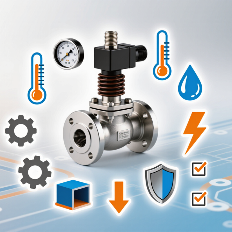
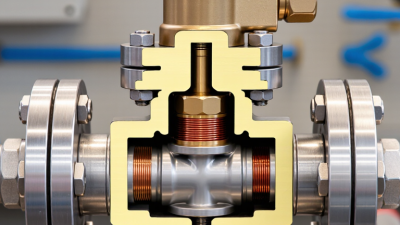
A direct-acting solenoid valve uses an energized coil to create a magnetic field. The field lifts or moves a metal plunger, opening the orifice directly. When power stops, a spring usually returns the plunger. Unlike pilot-operated designs, this action does not depend on downstream pressure. It can function at zero differential pressure, which matters in vacuum lines, small dosing systems, and low-flow equipment. The response is immediate, but not always gentle.
Selection begins with the medium. Water, air, steam, oils, and aggressive chemicals require different sealing materials and body metals. Check pressure, temperature, orifice size, flow coefficient, voltage, duty cycle, and enclosure rating. A larger orifice may increase flow, yet it can raise power demand and closing shock. The U.S. Department of Energy reports that compressed-air leaks can waste 20–30% of compressor output, so valve leakage deserves measurement, not guesswork. ISO 1219-1 also provides standardized symbols for fluid-power diagrams, helping technicians verify the valve’s actual function. In field testing, listen for a sharp click, inspect heat around the coil, and watch pressure recovery. Catalog values can mislead. I have seen a valve pass a bench test but struggle after dust entered the line. A filter, correct seal, and accessible manual override may matter more than a slightly faster response.
Defining pressure, flow, and port requirements prevents most selection errors. Record the medium, inlet pressure, outlet pressure, temperature, and expected pressure changes. A direct acting solenoid valve can operate without a minimum pressure difference, but its maximum pressure rating still matters. Check both normal and peak pressure. A brief pressure spike can damage a valve that appears suitable on paper. Do not confuse gauge pressure with absolute pressure. That mistake is easy to make.
Flow demand should be expressed clearly, such as 12 liters per minute at 3 bar differential pressure. Or use the required Cv or flow coefficient. A larger orifice usually allows more flow, but it may increase power consumption and closing shock. For gases, state the upstream pressure, downstream pressure, temperature, and whether flow is continuous. For liquids, consider viscosity and suspended particles. Clean water behaves very differently from thick oil.
Port requirements include connection type, nominal size, installation space, and pipe material. A 1/2-inch port does not automatically provide the needed flow. Internal passages decide that. Match the valve body and seals to the medium, not just the pipe thread. I once treated port size as the main criterion; the result was poor response and unnecessary noise. That was a useful correction. Leave room for a filter, wiring, and future maintenance. Practical details often matter more than a perfect catalog value.
Choosing a direct acting solenoid valve starts with the fluid, not the connection size. I have seen small seal errors cause leaks, swelling, and delayed valve movement. The valve body should match the environment around it. Brass often suits clean water and general service. Stainless steel handles corrosive surroundings more confidently. Plastic bodies can work well, but temperature and pressure limits need careful checking.
Seal selection is more complicated than it appears. NBR is practical for air, water, and many general oils. EPDM performs well with hot water and steam, but it is usually unsuitable for petroleum-based fluids. FKM tolerates many oils and higher temperatures, although certain chemicals can still damage it. PTFE offers strong chemical resistance and low friction. It may, however, require attention to sealing force and operating temperature.
Do not trust a material chart alone. Check the exact fluid concentration, temperature range, pressure, and switching frequency. A seal that survives a cold bench test may fail beside a hot pump. I once treated “chemical resistant” as a complete answer; it was not. Request compatibility data from a qualified supplier, then compare it with real operating conditions. Also inspect moisture, dust, and outdoor exposure. These details often decide whether the valve lasts months or several years.
A direct acting solenoid valve can open without system pressure, but correct electrical selection remains essential. Check the coil voltage against the actual supply, not only the equipment label. A 24-volt DC coil may fail under long cable runs and voltage drop. Confirm AC or DC operation, allowable tolerance, power consumption, and duty cycle. Measure voltage at the valve terminals during startup. That small test often reveals hidden wiring problems.
Response time should match the process, especially in dosing, pneumatic control, and safety-related equipment. Manufacturers usually specify opening and closing times under defined conditions. Fluid pressure, viscosity, temperature, and pipe size can change those figures. Test the valve with the real medium whenever possible. Fast is not always better. A rapid closure may create pressure shock, noise, or unstable flow. Keep that in mind.
Operating conditions deserve equal attention. Check media compatibility, ambient temperature, humidity, mounting position, and expected contamination. A clean laboratory sample can mislead. In field inspections, fine particles often delay movement or damage the sealing surface. Add filtration when the application allows it. I have also seen engineers choose a valve from nominal port size alone. That shortcut caused unnecessary pressure loss. Review flow requirements, response data, and maintenance access together. Some assumptions will be wrong; revise them after testing.
Choosing a direct acting solenoid valve starts with the actual installation, not the catalogue image. Confirm fluid type, pressure range, temperature, flow demand, port size, and response time. Direct acting models can operate at zero differential pressure, but small orifices may restrict flow. Measure pipe dimensions and available clearance. Tight cabinets turn simple replacements into awkward work. Check coil voltage and electrical protection before ordering. A wrong voltage can stop a line quickly. Keep the valve accessible. This matters later.
During maintenance, inspect seals, plunger movement, wiring, and signs of heat or corrosion. Use clean filtration when the process allows it. Dirt often causes intermittent closing, which is harder to diagnose than total failure. Ask how the valve will be isolated and drained. Safe access and approved procedures should guide the design. Keep spare coils and critical seals only when compatibility and storage life are confirmed. Maintenance records should include cycle counts, leak observations, and replacement dates. Field experience shows that neglected connectors cause surprisingly many faults. I once focused on the valve and missed a loose terminal. Keep it accessible.
Total cost includes purchase price, fittings, labor, energy, downtime, testing, and disposal. A cheaper valve may need frequent cleaning or special adapters. Compare expected cycles and service intervals, not price alone. Check replacement-part availability and technician familiarity. Estimate the cost of one unplanned stoppage. It may exceed the original valve price. Review the estimate with installation and operations staff. Their concerns can expose assumptions that spreadsheets hide. Leave room for uncertainty. Actual service conditions rarely match the specification sheet.
| No. | Selection Tip | Key Factor to Check | Installation Impact | Maintenance Impact | Total Cost Consideration | Practical Selection Guidance |
|---|---|---|---|---|---|---|
| 1 | Confirm the pressure requirement | Minimum and maximum operating pressure, including differential pressure | Direct-acting valves can operate at zero differential pressure, which may simplify piping and commissioning. | Correct pressure selection reduces chatter, incomplete opening, and premature seal wear. | Avoids the cost of regulators, bypass arrangements, or replacement caused by unsuitable pressure conditions. | Choose a direct-acting design when the system has low or fluctuating pressure and the required flow is relatively modest. |
| 2 | Size the orifice and flow capacity correctly | Required flow rate, media state, valve coefficient, and line size | A smaller orifice can reduce valve size but may require more installation time if multiple valves are needed for the total flow. | Oversizing may increase energy use and cause unstable control; undersizing can create excessive pressure loss. | The lowest purchase price is not economical if the valve restricts production flow or needs frequent replacement. | Calculate flow under actual pressure and temperature conditions rather than matching the valve only to the pipe diameter. |
| 3 | Match the valve materials to the medium | Body, seal, diaphragm, and plunger material compatibility | Compatible materials reduce the need for extra isolation components and special installation precautions. | Chemical attack, swelling, embrittlement, or corrosion can cause leaks and shorten service intervals. | Material compatibility usually costs less than repeated seal replacement, contamination, or unplanned downtime. | Check compatibility with the actual concentration, temperature, cleanliness, and phase of the medium. |
| 4 | Select the correct electrical rating | Voltage type, nominal voltage, frequency, power draw, and connector configuration | A matching rating allows direct connection to the control circuit without an additional transformer or interface relay. | Incorrect voltage can cause coil overheating, failure to actuate, or repeated electrical faults. | Lower-power coils can reduce operating energy, especially in applications with long energized periods. | Verify AC or DC supply, voltage tolerance, inrush behavior, and control-panel capacity before ordering. |
| 5 | Check duty cycle and heat generation | Continuous or intermittent operation, ambient temperature, and coil surface temperature | Continuous-duty suitability prevents the need for additional cooling or frequent shutdowns. | Excess heat accelerates coil insulation aging and can affect nearby seals and wiring. | A suitable continuous-duty coil can reduce energy losses and replacement frequency over the valve’s service life. | Use a continuous-rated coil where the valve remains energized for extended periods; confirm the temperature class. |
| 6 | Evaluate installation orientation and space | Permitted mounting position, access clearance, flow direction, and pipe alignment | Adequate clearance makes wiring, tightening, testing, and future coil replacement easier. | Good access reduces maintenance labor and lowers the risk of damaging connectors or pipe threads. | A compact valve may save space, but poor access can increase labor and downtime costs. | Follow the installation orientation specified for the valve and provide enough room to remove the coil and service seals. |
| 7 | Consider contamination control | Particle size, filtration, flushing, and cleanliness of the upstream piping | An upstream filter and clean pipework may add initial components but help prevent installation-related failures. | Particles can obstruct small orifices, prevent full closure, and increase inspection or cleaning frequency. | The cost of basic filtration is often lower than repeated valve cleaning and production interruptions. | Flush new piping before connection and use filtration appropriate to the medium and the valve’s smallest internal passage. |
| 8 | Review sealing and leak-prevention requirements | Thread type, gasket arrangement, seal material, leakage class, and tightening procedure | Correct fittings and sealing methods reduce installation leaks and avoid over-tightening damage. | Regular leak checks can identify seal aging, loose connections, and valve-seat wear before failure. | Leakage can increase media consumption, safety risk, and compliance costs, particularly with hazardous or compressed media. | Use compatible thread sealants and follow the specified tightening method; do not allow sealant to enter the valve passage. |
| 9 | Compare serviceability and spare-part availability | Replaceable coil, seal kit, plunger, connector, and documented service procedure | Modular parts can simplify commissioning and reduce the need to remove the entire valve body. | Replaceable wear components support planned maintenance instead of complete valve replacement. | Part availability, labor time, inventory carrying cost, and downtime should be included in lifecycle cost. | Select a design with clear part identification and documented maintenance instructions for critical applications. |
| 10 | Calculate total cost of ownership | Purchase price, installation labor, energy, inspection, spare parts, downtime, and disposal | A valve with suitable connections and simple wiring may have a higher purchase price but lower installation labor. | Service intervals, repair time, replacement parts, and diagnostic access affect ongoing operating expense. | Compare the expected five-year cost rather than purchase price alone: acquisition + installation + energy + maintenance + downtime. | Prioritize reliability and serviceability when a valve failure can stop production or create a safety-related shutdown. |
| Cost comparison note: Total cost varies with application conditions. Evaluate the valve using actual pressure, flow, medium, temperature, duty cycle, energy price, maintenance labor rate, and the financial impact of downtime. | ||||||