How to Choose a Wafer Type Butterfly Valve?

Choosing the right Wafer Type Butterfly Valve affects flow control, leakage prevention, maintenance time, and plant safety. This valve fits between pipeline flanges, making it compact and cost-effective. However, compact does not mean universally suitable. A valve handling clean cooling water may fail quickly in abrasive slurry service.

This guide explains the practical details engineers should check before ordering. Begin with the medium, operating pressure, temperature, and required flow rate. Then compare seat materials, disc alloys, shaft design, and actuator performance. EPDM may suit water systems, while chemical service may require PTFE or another compatible material. The correct choice depends on actual operating conditions, not just the product label.

Field experience shows that installation space often changes the final decision. A crowded pipe rack may require a low-profile actuator. A large valve may need lifting support during maintenance. Inspectors should also review pressure ratings, flange compatibility, testing records, and applicable industry standards. Reliable manufacturers provide clear drawings and traceable material information.

Small details matter.

No selection is perfect. A valve with excellent corrosion resistance may cost more or operate less efficiently. A cheaper option may increase replacement work later. Engineers should challenge assumptions, verify manufacturer data, and consider the complete service life. This article offers a practical framework for comparing valve designs and choosing a Wafer Type Butterfly Valve with greater confidence. Further review may still be necessary for unusual media, severe temperatures, or critical process lines.

How to Choose a Wafer Type Butterfly Valve?

What Is a Wafer Type Butterfly Valve?

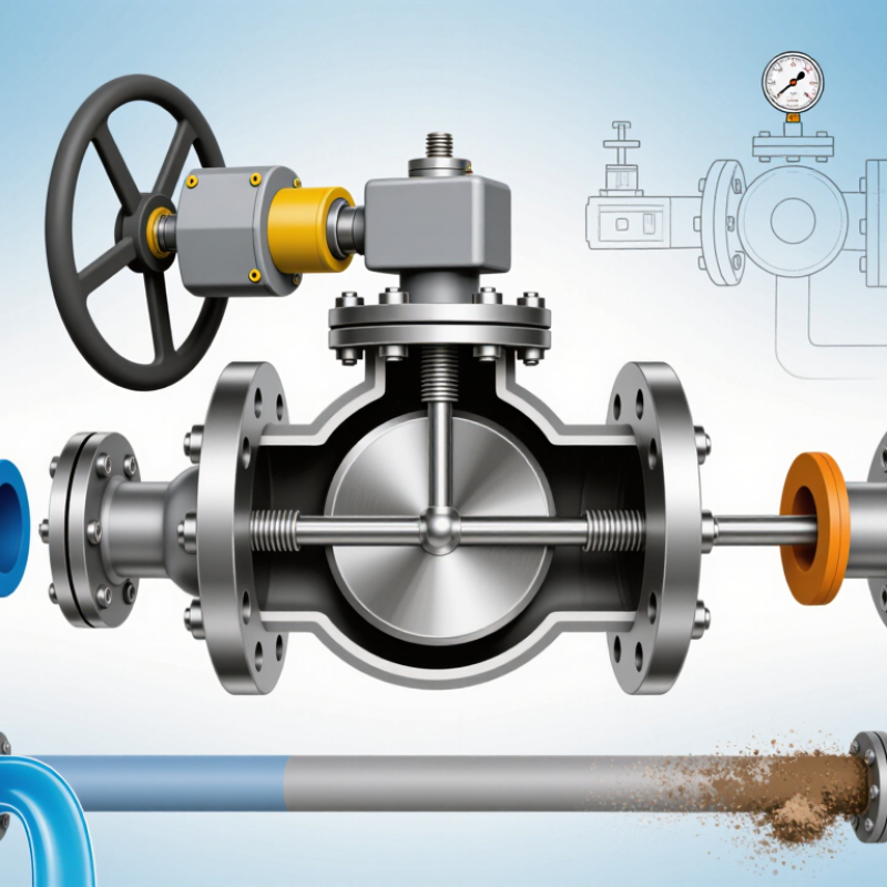
A wafer type butterfly valve is a compact quarter-turn valve installed between two pipe flanges. Its thin body reduces weight, space, and material use. Inside, a circular disc rotates around a stem to control fluid flow. When the disc aligns with the pipe, flow passes through. When it turns across the pipe, the passage closes.

The valve does not usually provide the same flange connection as a lug or flanged design. The surrounding pipe flanges hold it in position. This detail matters during installation. Flange alignment must be accurate, and the valve must fit the pipeline’s pressure rating. A damaged seat, uneven bolts, or poor centering can cause leakage. Small errors become visible quickly.

Choosing this valve type requires more than checking its diameter. Review the fluid, operating temperature, pressure, and expected cycling frequency. Clean water, air, mild chemicals, and abrasive slurries may require different seat and disc materials. Manual handles suit occasional adjustment, while actuators help with frequent or remote operation. In practical inspections, I would also check clearance for the disc because nearby elbows can restrict its movement. A compact valve is not automatically the best valve. That assumption deserves a second look.

How Does a Wafer Type Butterfly Valve Work?

How to Choose a Wafer Type Butterfly Valve?

A wafer type butterfly valve sits between two pipe flanges. Its slim body saves space and reduces installation weight. Inside, a circular disc controls the passage. The disc connects to a stem, which turns through roughly 90 degrees. When the disc faces the flow, the passage opens. When it turns across the pipe, the valve closes.

Simple operation.

During maintenance checks, technicians usually inspect the disc edge, stem, seat, and flange alignment. A resilient seat presses around the disc and limits leakage during closure. However, poor alignment can create uneven pressure and accelerate seat damage. Tightening the bolts in an uneven pattern may cause similar problems. This detail is often underestimated.

Choosing the valve requires more than matching the pipe diameter. Check the working pressure, temperature, fluid properties, and flange standard. Abrasive liquids may wear soft sealing materials quickly. Hot fluids can also exceed the seat’s practical temperature range. For clean water, a resilient-seated design may provide reliable shutoff. For demanding service, a metal-seated option may deserve closer review.

Actuation matters too. A handle suits smaller lines and occasional operation. A gearbox or automated actuator can improve control on larger systems. Confirm the required operating torque, especially when deposits may collect around the disc. No valve is perfect. Real performance depends on correct sizing, careful alignment, suitable materials, and regular inspection.

How to Choose a Wafer Type Butterfly Valve? - How Does a Wafer Type Butterfly Valve Work?
Wafer Type Butterfly Valve Selection and Operating Guide
Selection Dimension Typical Options or Data How It Affects Valve Selection Practical Recommendation
Valve Function
  • On/off isolation
  • Throttling or flow regulation
  • Emergency shutoff
A butterfly valve uses a rotating disc to open, restrict, or stop flow. Continuous throttling can increase turbulence, wear, and seat damage if the valve is not designed for control service. Use a correctly sized butterfly valve for isolation. For frequent modulation, confirm the valve, actuator, seat, and control characteristics are suitable for throttling.
Operating Principle Quarter-turn rotation, normally about 90° from fully closed to fully open. The stem transfers torque to the disc. When the disc is parallel to the pipeline, flow resistance is low; when it is perpendicular, the passage is closed. Allow sufficient actuator torque for line pressure, seat friction, temperature, and any solids or deposits in the medium.
Installation Style Installed between two pipe flanges; the valve body is held in position by flange bolts or studs. A wafer body is compact and lightweight, but it generally does not provide independent end support like a lug-style body. Verify the valve is suitable for the applicable flange standard, flange face, bolt pattern, pipe alignment, and available installation space.
Nominal Size Commonly available in approximately DN50 to DN1200, with larger sizes available for specific designs. Size affects flow capacity, pressure drop, actuator torque, face-to-face dimensions, weight, and installation cost. Select the smallest valve that meets the required flow without creating excessive pressure loss. Do not select only by matching the pipe size.
Pressure Class Typical examples include PN6, PN10, PN16, Class 150, and other design-specific ratings. The allowable pressure depends on the body, disc, shaft, seat, temperature, and applicable design standard. The seat rating and body rating may differ. Confirm both the maximum working pressure and the pressure-temperature rating at the actual operating temperature.
Flow Medium
  • Water and treated water
  • Air and noncorrosive gases
  • Seawater or mildly corrosive fluids
  • Slurries or fluids containing suspended solids
Solids, chemicals, abrasives, and gas service can affect seat wear, disc erosion, leakage performance, and material compatibility. Provide the medium, concentration, viscosity, solids content, cleanliness, and required leakage class before selecting the valve.
Body Material
  • Ductile iron: general water and utility service
  • Carbon steel: higher mechanical strength and selected industrial service
  • Stainless steel: improved corrosion resistance
  • Special alloys: severe or highly corrosive service
Material choice influences corrosion resistance, pressure capability, temperature range, weight, and cost. Choose the body according to the fluid chemistry, external environment, pressure, temperature, and applicable material standard.
Disc Material
  • Ductile iron with protective coating
  • Stainless steel
  • Higher-alloy or coated disc materials
The disc is continuously exposed to the process medium and can be vulnerable to corrosion, erosion, and cavitation. Use a corrosion- and erosion-resistant disc when the fluid contains chemicals, salts, suspended particles, or dissolved gases.
Seat Material and Temperature
  • EPDM: commonly used for water and some mild aqueous services
  • NBR: commonly used where oil resistance is needed
  • FKM: suitable for selected higher-temperature or chemical services
  • PTFE or metal seats: selected for special chemical or temperature requirements
The seat is usually the limiting component for temperature and chemical compatibility. Actual limits vary by formulation and design. Check the manufacturer’s pressure-temperature chart and compatibility data rather than relying on the seat name alone.
Temperature Range Common resilient-seat designs may operate roughly from −20°C to 120°C, depending on the seat compound and service conditions. Temperature changes can reduce elastomer strength, accelerate aging, alter sealing force, and change the allowable pressure. Specify minimum and maximum operating temperatures, including startup, shutdown, cleaning, and upset conditions.
Leakage Requirement
  • Bubble-tight shutoff for many resilient-seat valves
  • Defined leakage class for tested control or isolation service
  • Allowable leakage for metal-seat designs
Leakage performance depends on seat design, disc condition, operating pressure, temperature, installation, and test standard. State the required leakage class and test direction. Confirm whether the valve is rated for bidirectional or preferred-direction shutoff.
Actuation Method
  • Manual lever: smaller sizes and infrequent operation
  • Gear operator: larger sizes or higher operating torque
  • Pneumatic actuator: fast and repeated operation
  • Electric actuator: automated positioning and remote control
Actuator selection depends on breakaway torque, running torque, closing time, available power, duty cycle, and control requirements. Select the actuator using the complete torque curve, including a safety margin and the most demanding pressure and temperature condition.
Control Position
  • Normally open
  • Normally closed
  • Fail-open or fail-closed
  • Intermediate modulating position
Spring-return pneumatic actuators can provide a defined failure position. Electric systems may require a battery, spring-return unit, or other backup arrangement. Define the safe position after loss of air, electricity, signal, or control pressure before choosing the actuator.
Flow Capacity Capacity is commonly expressed using flow coefficient, such as Cv or Kv, and varies with valve size and opening angle. A larger valve is not automatically better; oversizing can reduce controllability and cause the valve to operate near the closed position. Use required flow, allowable pressure drop, fluid density, viscosity, and operating pressure to calculate the correct size.
Cavitation and Noise Possible when liquid pressure falls below vapor pressure inside or downstream of the valve. High pressure drop, high velocity, and unsuitable opening positions can cause noise, vibration, material damage, and unstable flow. Check pressure-drop limits and cavitation risk, especially in pumping systems and high-pressure liquid service.
Flange and Pipeline Compatibility Must match the pipeline flange standard, nominal size, pressure class, gasket arrangement, and bolt dimensions. Incorrect alignment or unsuitable flange faces can damage the seat, prevent full disc movement, or create external leakage. Use a centered installation, clean flange faces, the correct gasket arrangement, and an unobstructed pipe bore.
Maintenance Considerations Routine checks may include external leakage, actuator operation, bolt condition, corrosion, position indication, and unusual noise or vibration. Wear can result from incorrect alignment, excessive torque, incompatible chemicals, high velocity, or operating outside the rated range. Inspect according to service severity and isolate, depressurize, and drain the line before maintenance.
Key Advantages
  • Compact face-to-face length
  • Low weight compared with many multi-turn valves
  • Quarter-turn operation
  • Low pressure loss when fully open
  • Suitable for large pipeline diameters
These features can reduce installation space, actuator size, handling effort, and total system cost. Wafer butterfly valves are often suitable for water, HVAC, utility, and selected industrial applications where compact isolation is important.
Main Limitations
  • Disc remains in the flow path
  • Potential pressure drop at partial opening
  • Seat limitations at high temperature
  • Possible sensitivity to abrasive or incompatible media
The disc and seat design may make the valve unsuitable for certain pigging operations, severe abrasion, very high temperature, or demanding zero-leakage applications. Compare the valve with other designs when the line requires full unobstructed passage, severe-service trim, high-temperature metal sealing, or specialized cleaning.
Selection note: The pressure, temperature, size, flow-capacity, and material ranges shown are typical engineering reference values, not universal limits. Always verify the applicable design standard, pressure-temperature rating, material compatibility, leakage test requirement, flange dimensions, and actuator torque for the specific service.

Which Valve Materials and Specifications Suit Your System?

Choosing a wafer type butterfly valve starts with the medium, not the catalog photo. For clean water, EPDM liners and ductile iron bodies often provide practical service. Hydrocarbons usually require a compatible elastomer, such as FKM, and stronger body materials. Check temperature, pressure, concentration, and abrasive content together. A cold chemical can still damage a liner.

The NACE IMPACT study estimated global corrosion costs at about 3.4% of GDP, or 2.5 trillion dollars annually. That figure makes material selection more than a purchasing detail. For chloride-rich water, stainless steel may outperform standard carbon steel, but even stainless alloys have limits. Test the actual fluid when uncertainty remains. Small mistakes become expensive leaks.

Specify the valve against recognized requirements, including API 609 for butterfly valve design and ISO 5211 for actuator mounting. Confirm wafer dimensions, flange compatibility, pressure class, seat leakage rate, and shaft material. For hazardous or fugitive-emission service, ISO 15848 testing can strengthen the specification. Do not select by pressure rating alone. A valve rated for 16 bar may fail early if its liner sees excessive heat or incompatible chemicals. Field experience also matters: cycling frequency, suspended solids, dead-end installation, and maintenance access should appear on the datasheet. I would still challenge one assumption: “stainless steel” is not a universal corrosion solution.

How to Match Valve Size, Pressure, and Temperature Requirements?

Choosing a wafer type butterfly valve starts with the actual service conditions, not only the pipe diameter. Match the valve’s nominal size to the line, then verify flow velocity and required flow coefficient. An oversized valve may operate almost closed, causing unstable control and unnecessary wear. An undersized valve can create excessive pressure loss. Measure the medium, flow rate, and available pressure difference before selecting the disc diameter.

Pressure and temperature must be checked together. A valve rated for a certain pressure at room temperature may have a lower allowable pressure at elevated temperatures. Review the pressure-temperature chart for the complete valve assembly, including the body, disc, shaft, and seat. Water, steam, chemicals, and abrasive slurries require different materials and sealing designs. A metal seat may tolerate heat better, while an elastomeric seat can provide tighter shutoff within its temperature range. The choice is not always obvious.

Leave space for thermal expansion and inspect the flange alignment carefully. Poor alignment can load the shaft and damage the seat during the first operation. In field selection, I often see pressure checked but temperature ignored. That shortcut can be costly. Also verify the actuator torque, especially when the medium contains solids or the valve may remain closed for long periods. Use the manufacturer’s certified data, installation instructions, and applicable standards before approving the final size.

What Installation and Maintenance Factors Should You Consider?

How to Choose a Wafer Type Butterfly Valve?

What Installation and Maintenance Factors Should You Consider?

Installation quality often decides whether a wafer butterfly valve performs reliably. Check the pressure rating, temperature range, medium, and seat material first. Flanges must be aligned correctly. Even a small offset can rub the disc against the liner. Keep the disc slightly open during installation, then tighten bolts in a diagonal pattern. The pipeline should be flushed before fitting the valve. Welding debris is unforgiving.

Consider access for future servicing. The handle, gearbox, or actuator needs enough clearance for operation and removal. In dead-end service, verify the valve’s permitted pressure direction and configuration. For automated systems, confirm actuator torque across the full stroke, not only at the start. The U.S. Department of Energy reports that compressed-air leaks commonly waste 20–30% of compressor output. A poorly adjusted pneumatic actuator can increase that waste. Small errors become operating costs.

Maintenance should include visual checks, flange-bolt inspection, stem movement, and seat leakage testing. ISO 5208 provides recognized leakage classifications for industrial valves, helping teams define acceptance criteria. Record torque, cycle count, and operating conditions. Trends matter more than isolated readings. Replace damaged seals early, but do not tighten everything blindly. Excessive compression can accelerate wear. I have seen maintenance plans focus on the valve and ignore pipe strain. That assumption deserves another review. Periodic inspection intervals should reflect cycle frequency, fluid cleanliness, vibration, and the consequences of failure.